Weed control pumps are the core of the spraying circuit
As we know diaphragm pumps, installed on sprayers, are used in agriculture for spraying and weed control (see: 3 BIG ADVANTAGES OF USING DIAPHRAGM AGRICULTURAL PUMPS)
In short, the hydraulic circuit of a sprayer consists of a tank, a pump and nozzles.
The tank contains water or chemicals, the pump sucks from the tank, discharges through filters and hoses on the arms where the pressure is converted into speed in the jets, thus causing spraying.
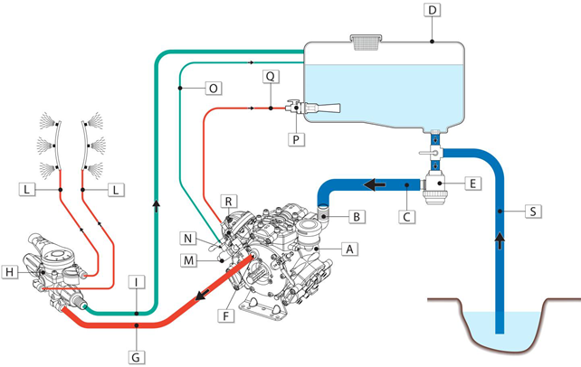
Several components are then added to this circuit to improve the level of performance, let's see together the main ones:
A - DIAPHRAGM PUMP
B - PUMP INLET
C - SUCTION LINE
D - TANK
E - SUCTION FILTER
F - PUMP OUTLET
G - PRESSURE LINE
H - REGULATOR CONTROL UNIT
I – REGULATOR BY-PASS
L - SPRAYING LINE
M - SAFETY VALVE
N - SAFETY VALVE BY-PASS
O – SAFETY VALVE BY-PASS LINE
P - AGITATOR
Q - AGITATION LINE
R – ANCILLARY OUTPUT
S - LOADING LINE
Suction line
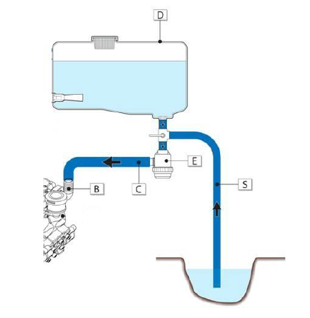
A pump can suck fluid from different sources:
from the main tank (D) when operating in spraying mode (i.e. during the distribution of plant protection products on the crops),
but also in agitation and by-pass mode from external water sources (S) such as canals, basins, water deposits (this function is used to load the main tank);
or from a clean water tank, to clean the tank, the pump and the circuit in the flush mode (this line is not shown in the diagram for sake of simplicity).
Recommendations for a well-functioning circuit:
- The outlet from the tank must be positioned at the very bottom, to ensure complete drainage and avoid stagnation and sedimentation;
- A suction filter (E) is always recommended on the suction line having a correctly sized flow rate and mesh, in order to avoid that stones or sand can damage the pump.
- The suction and loading lines must be made of reinforced plastic hoses (spirals), rigid enough to counteract internal vacuum, preventing the walls from sticking due to suction, thus throttling the inlet.
- The inside diameter must be equal to the outside diameter of the pump inlet fitting (B).
- A 3 or 4-way ball valve must be positioned at the inlet of the suction filter (E), to switch from the loading mode to the spraying and flush mode.
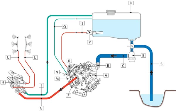
Delivery lines
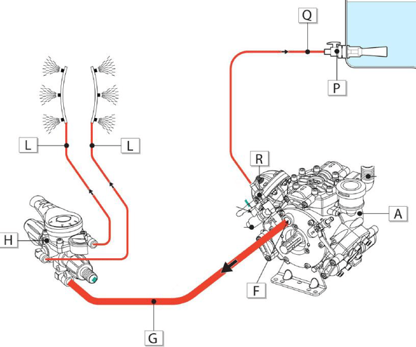
A pressure/delivery line mainly consists of a flexible rubber hose with suitable characteristics in terms of size and resistance to pressure, so as to meet the treatment specifications.
The pressure/delivery lines (marked in red) are normally of two types:
- spraying lines: these are used to supply the spraying nozzles.
The pressure line (G) connects the pump (F) to the regulator control unit (H) and then to the spraying lines (L); - agitation lines: the agitator (P) must be positioned at the bottom of the tank (D) in order to keep the liquid mixed, thus avoiding the deposit of chemicals on the bottom. The agitator is powered by an ancillary output (R).
In the figure, the output is located on the pump's delivery manifold, but an agitation line can also be achieved by mounting a three-way valve on the pressure/delivery line.
By-pass lines
The by-pass lines are required for returning the liquid to the tank.
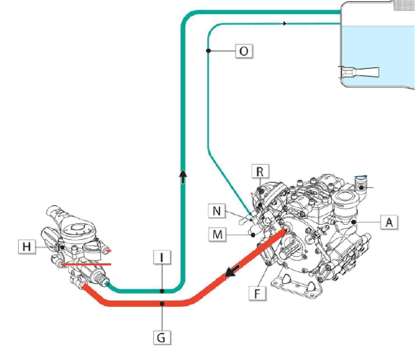
They consist of:
- main by-pass line: line (I) returns the overflow from the regulator control unit to the tank;
- safety valve by-pass (M): in case of pressure peaks it returns the overflow to the tank, through the line (O), avoiding breakage of the pump and environmental contamination.
The by-pass discharge holes should be located in the upper part of the tank, since in a low position, the water inside the tank would create a strong counter-pressure, thus obstructing the regular return with losses of performance and early pump failures.
The spraying line (L) and the agitation line (Q) are full pressure lines, while the by-pass lines are lower pressure lines.
Pressure regulator
The diaphragm pump, like any other positive displacement pump, must also include a pressure regulator equipped with by-pass on the delivery line, which has a dual function:
- adjust the desired pressure;
- do not exceed the maximum pressure allowed by the pump.
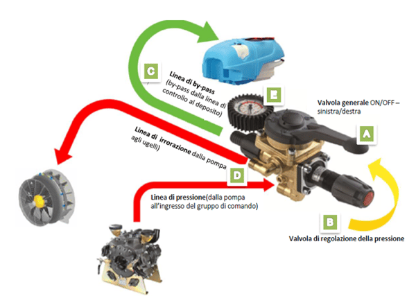
Normally, a pressure regulator (or control unit) is equipped with:
- a master valve for the main shut-off
- a pressure regulation valve (optional in some versions)
- a by-pass: for the return of the overflow to the tank
- section valves (or taps) to distribute the flow to the various lines
- a pressure gauge.
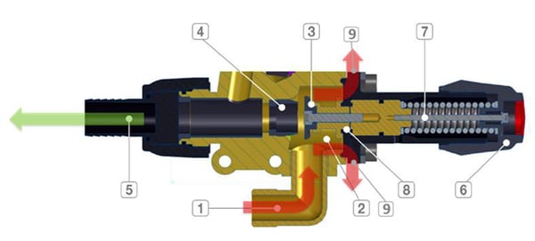
During the typical configuration of a control unit, the pumped liquid flows through an inlet (1) and reaches an inner chamber (2), the latter being directly connected to the outlets, i.e. the spraying lines (9).
The pressure regulation system consists of a valve (3) and its seat (4).
Through this seat, the liquid can be discharged towards the by-pass line (5).
Pressure is adjusted by operating a knob (6) that acts on a spring (7), which is in turn connected to a valve. Finally, the diaphragm (8) separates the liquid from the spring-knob system.
To learn more visit our page: AGRICULTURE DIAPHRAGM PUMPS or download our Guide: