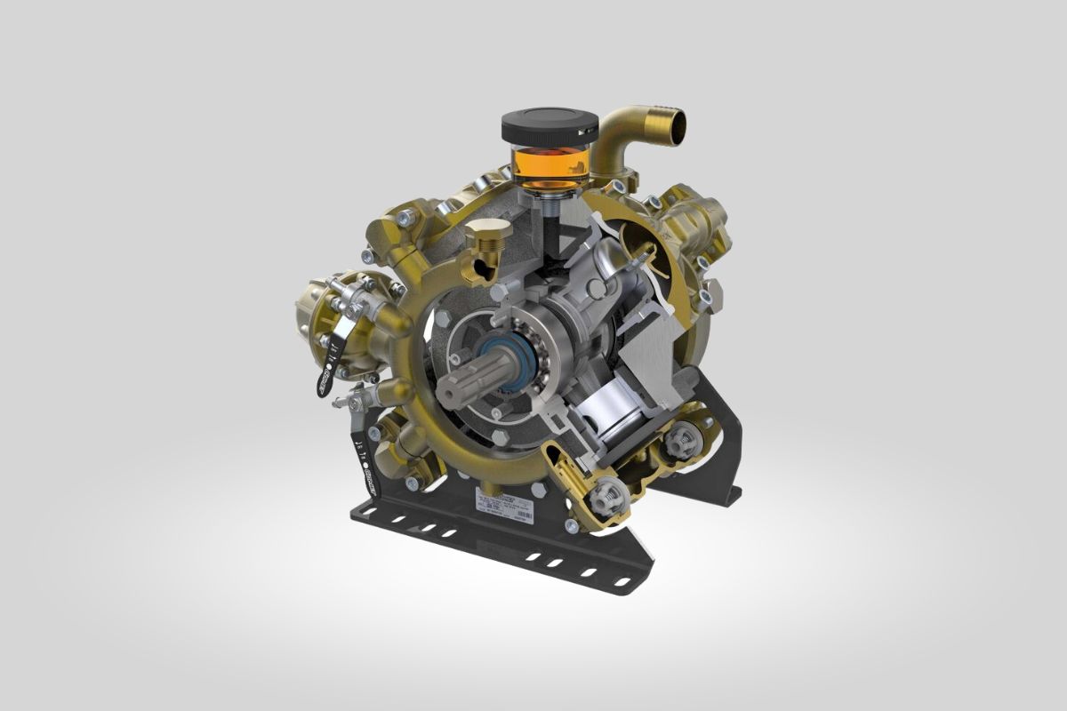
A diaphragm pump is composed of two basic parts: the transmission and the pumping unit. The diaphragm pump
converts the mechanical energy of a motor into the dynamic pressure of the pumped fluid.
The transmission transfers the mechanical energy from the motor to the pump and the pumping unit transforms the mechanical energy into fluid pressure.
Transmission
The rotational drive shaft (A) receives energy from the engine which can be electric, combustion or hydraulic.
The conversion of the rotational movement (curved arrows) into oscillatory motion (straight arrows) is produced via a connecting rod-crank system (B), which connects the shaft to the piston (C) which runs inside a cylinder or sleeve (D).
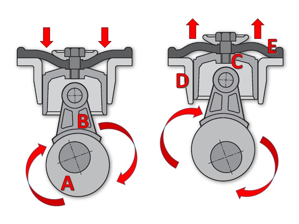
The transmission system is very similar to a two-stroke combustion engine, with the difference that in the engine the power is transmitted from the piston to the shaft, while in the pump, power is transmitted from the shaft to the piston and to the diaphragm.
All the mechanical components are contained in a crankcase in an oil bath with a specific lubricant (normally a 10W40, except for some pump models).
The piston is screwed to the central part of the diaphragm (E), which causes its oscillation and the periodic movement of suction and discharge.
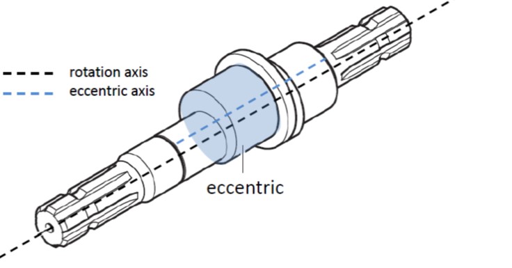
The shaft realizes the conversion from rotational to oscillating movement, by way of an eccentric linked to the connecting rod. An eccentric is a circular-shaped element with a rotation axis external to the axis of the rotational shaft. Since the main application of the diaphragm pump is agricultural spraying, it has traditionally been given a rotational speed corresponding to that of the tractor’s PTOs : 550 RPM.* 800 rpm pumps are currently also available, such as Comet BP - HS that can also meet the requirements of modern tractors.
The shaft can receive power from various types of motors and in various ways. It is also used as a transmission element for actuating extra gear. The Comet range, therefore, offers two different configurations: single shaft, with a single p.t.o. (usually on the delivery side) and through shaft, with double p.t.o. The second stub is used to transmit power to extra gears.
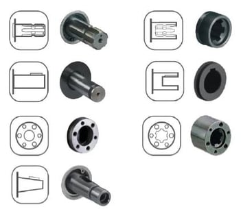
Configurations of the power-take-offs can also be multiple, this is the Comet range:
- splined 1” 3/8 (male or female)
- cylindrical (male or female)
- 6-hole shaft (male or female)
- conical (male only)
Read also: EVERYTHING YOU NEED TO KNOW ABOUT DIAPHRAGM PUMPS
Pumping unit
The pumping unit in a diaphragm pump consists of: diaphragm, suction valve, pumping chamber and delivery valve.
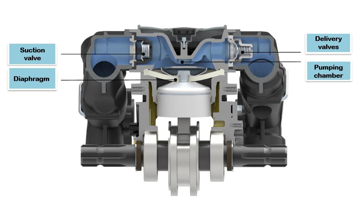
Diaphragm
The diaphragm is a rubber disc screwed on the top of the piston with a bolt and a fixing disc, that keep it aligned during its strokes. The diaphragm is the main element of the pump since it has two crucial functions:
- it alternately expands and collapses the volume of the pumping chamber, this way enabling the pumping action.
- it separates the pumping chamber from the transmission system, preventing the fluid from coming into contact with the mechanical parts and oil which would lead to serious damage risks for the pump.
Two distinct features define a diaphragm: strength (expressed by a numerical value that measures plastic deformation) and its material (the level of elasticity and hardness of the material affects diaphragm life, stiffness and resistance to chemical and environmental corrosion).
Diaphragms are available in three different materials:
NBR – Nitrile buna rubber: excellent elasticity and mechanical resistance to solid and abrasive particles, together with good chemical resistance. For this reason, it is the most popular diaphragm in the air blast sector (citrus, olive crops and fruit trees in general).
Viton® - Fluoroelastomer DuPont™: offers proven resistance to chemical products and extreme temperatures. It’s the most suited fluoroelastomer for special applications, thanks to its extreme chemical resistance.
Desmopan® - Thermoplastic elastomer polyurethane supplied by Bayer: excellent elasticity and hardness; high resistance to compression, flexion and abrasion. Good resistance to wear, hydrolysis, oxygen, solvents and diluted alcohols or basics. It is the most recommended material for boom sprayers.
Read also: 3 BIG ADVANTAGES OF USING A DIAPHRAGM PUMP
Suction and delivery valves
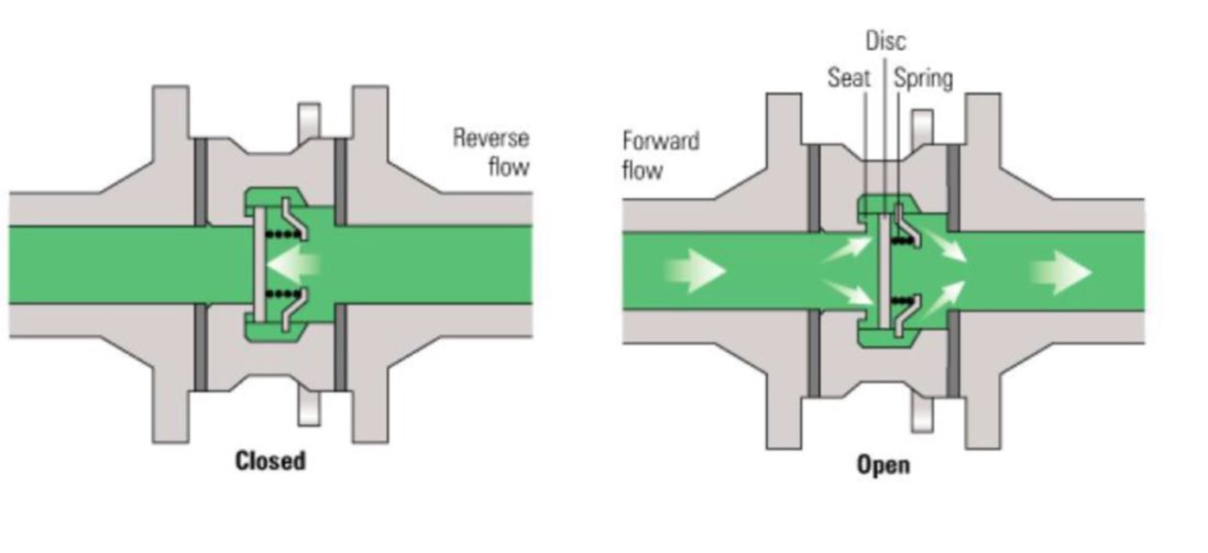
Each pumping unit is equipped with two valves: one for suction and one for delivery.
The diaphragm pump valves are also called non-return (or one-way) valves, as their purpose is to allow flow in one direction and completely block flow in the opposite direction.
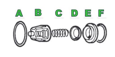 Elements of the non-return valves
- A, F : O-ring
- B : By-pass guide or cage
- C : Compression spring
- D : By-pass or disc
- E : Locking ring
The function of the O-rings (A, F) is to create a watertight sealing between the valve and the pump head.
The by-pass guide (B) consists of a techno-polymer cage, with the function of maintaining by-pass and spring aligned during their strokes. The slots (or ports) of the guide allow the correct liquid dosage, therefore they are vital elements and require a very advanced design technology, which combines high load and correct liquid flow.
The spring (C) has the function of helping by-pass closure, by exerting pressure so as the by-pass remains pressed on the locking ring (E). It is manufactured in stainless steel and the pressure must be perfectly balanced during the design studies, so to allow maximum speed in opening and closing at the preset pressure.
The by-pass (D) is an oscillating element, which moves in sync with the diaphragm. Its function is to open and close the valve. It consists of a stainless steel disc, with a trapezoidal or semi-spherical shape, thus improving sealing and sliding inside the guide. The locking ring (E) is the by-pass seat. This is a fixed element and consists of a stainless steel ring, its shape being complementary to that of the by-pass.
During the closing phase, the spring, calibrated at a certain pressure, supports the by-pass onto the locking ring.
During the opening phase, the water pressure overcomes the load of the spring, which compresses thus allowing detachment of the by-pass from the sealing ring, thus giving free passage to the fluid. The two valves (suction and delivery) are positioned in-line and work in an alternative and opposite way.
Pumping chamber (or displacement cavity)
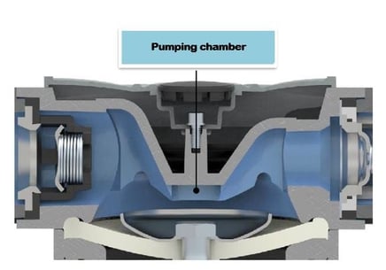 The pumping chamber is where the diaphragm stroke generates alternative volume contractions and expansions. In practice, it is the space between the head’s hollow and the upper face of the diaphragm. The internal shape of the head has a fundamental effect on pump performance. For this reason, its internal design has a “dome” concave shape, that allows the pump to reach the highest levels of pressure, vacuum, priming as well as improving overall efficiency. As this part is subject to heavy pressures and wearing process, the heads are normally designed in heavy-duty materials like brass, anodized aluminum, plastic-coated aluminum or techno polymers.
Other components of the diaphragm pumps
Manifolds
Manifolds are pipes that gather the multiple pumping units, so that the pump has a single suction line and a single delivery line, in order to simplify its installation. The delivery manifold gathers the fluid from several pumping chambers and conveys it to a single suction line. Its internal pressure can be very high and cause significant damage. For this reason, it must be equipped with a safety valve.
The suction manifold gathers the fluid from the suction line and distributes the same to several pumping chambers. It has no special strength requirements, as the internal pressure is negative.
Manifolds can be internal or external. Internal manifolds have a more compact design together with a competitive price (fewer components). External manifolds ensure higher resistance together with a lower risk of damage should the pump break.
Materials are another important variable, as they affect pressure and chemical/abrasion resistance. Brass, aluminum (anodized or plastic coated) and techno-polymers are the most commonly used materials. Last generation manifolds are equipped with a water discharge valve, so that they can be emptied before work stops in winter, avoiding frost damage.
Fittings
Both manifolds are equipped with a hose tail, which can be straight or curved and connect the pump to the machine circuit.
The suction fitting generally consists of a hose tail made of nylon or polypropylene as there is no pressure issue on the suction line.
The delivery fitting and, if present, the delivery taps are made of nylon or propylene on low-pressure pumps up to 20 bar and of brass on high-pressure pumps up to 50 bar.
Correct dimensioning of fittings is extremely important to avoid damage, first of all cavitation (link). For this reason, Comet's recommendations about the sizes of suction and delivery fittings should be strictly complied with.
Safety valve
The purpose of a safety (or pressure relief) valve is to reduce the consequences of overpressures on the delivery line. Safety valves are equipped with a spring-loaded bypass, calibrated at a certain pressure. The bypass opens whenever fluid pressure exceeds the spring pressure. This allows overpressure to be discharged, thus avoiding the breakage of tubes.
PTO guards
Farm safety research has shown that a high percentage of farming accidents are PTO-related. PTO guards prevent the operator or other persons from coming into contact with the rotary components, which represent an extreme danger to safety. On this point always remember that it is essential to approach the pump only when the machine has completely stopped. PTO guards can be mounted and removed very quickly.
Oil compensator
The oil compensator is a transparent receptacle which contains lubricating oil and is connected to the oil bath inside the crankcase. The oil compensator is used to check the correct oil level and refill it if necessary. This way the diaphragms can be oil-loaded during the delivery stroke and the mechanical parts are always lubricated.
That’s why the oil compensator is always placed on top of the pump and the oil level must always be above the line of the highest diaphragm.
The other vital function of the oil compensator is to act as a diaphragm breakage warning. In this case, oil and water mix together thus creating an emulsion inside the crankcase, recognizable by its typical milky color inside the oil compensator. If this happens, it is necessary to intervene immediately and replace damaged diaphragms to avoid further problems.
Pressure accumulator (or pulsation dampener)
The function of the pressure accumulator is to minimize or eliminate pulsations, prevent potential pipe hammering, reduce the load on the pump itself and reduce noise; in this way, pumps will have decreased wear and a longer life.
The accumulator is installed on the delivery manifold (or remotely on the line) and, thanks to the compressed air-charge, it absorbs the vibrations generated by the oscillating movement of the diaphragms.
Most of the vibrations are harmonized by synchronizing the stroke of the different pistons (phasing process). For this reason, pumps with more than 4 diaphragms, that is those with 5 or 6 diaphragms, do not require a pulsation dampener, since they have an excellent linear flow rate.